Highlights
Sub-nanosecond Synchronisation
Provides sub-nanosecond accuracy and picoseconds of precision synchronization for devices connected to an ethernet network.
Deterministic Data Transfer
Sends data across the network with a known maximum latency to trigger synchronized events.
Large networks
Thousands of devices can be connected to the same network, which can span more than 1000km
Keywords
Sub-nanosecond synchronization, deterministic data transfer, timestamping, trigger distribution, ethernet networks
White Rabbit (WR) is a technology developed at CERN to provide sub-nanosecond accuracy and picoseconds precision of synchronisation for the LHC accelerators chain.
CERN developed WR as an open-source hardware, with primary adoption by other research infrastructures with similar challenges in highly accurate synchronization of distributed electronic devices. It is currently deployed in numerous scientific infrastructures worldwide. White Rabbit has the potential to be commercialised and introduced into different industries, including telecommunications, financial markets, smart grids, space industry and quantum computing.
Explore the technology specifics:
What is it? Technical description
White Rabbit (WR) is a technology developed at CERN to provide sub-nanosecond accuracy and picoseconds precision of synchronisation for the LHC accelerators chain. It was first used in 2012 and since then has been showcasing its diverse industrial applications outside the field of particle physics. On 16 June, the Institute of Electrical and Electronics Engineers (IEEE) updated the Precision Time Protocol industry-standard (PTP) incorporating the White Rabbit PTP extension and thus maximising its adoption by industry and other partners in their pursuit to build innovative solutions to address world challenges.
CERN developed WR as open-source hardware, with primary adoption by other research infrastructures with similar challenges in highly accurate synchronization of distributed electronic devices. The R&D process and all knowledge gained throughout the development has been made available through CERN’s Open Hardware Repository. This gives other organisations and companies the freedom to use and modify existing developments. Through proactive engagement of CERN’s Knowledge Transfer group and Beam Controls group, a larger group of companies and organisations connected to the development of hardware, software, and gateware for WR switches and nodes. The WR ecosystem quickly grew to include several organisations, developing open hardware for widespread benefit. This collaborative approach brought improvements to the original concept, allowing CERN to also benefit from the new developments as well.
This new Ethernet-based technology, which ensures sub-nanosecond synchronisation and deterministic data transfer, is now deployed in numerous scientific infrastructures worldwide. It has shown its innovative potential by being commercialised and introduced into different industries, including telecommunications, financial markets, smart grids, space industry and quantum computing.
What is Precision clock synchronisation?
It is the IEEE Standard for a Precision Clock Synchronization Protocol for Networked Measurement and Control Systems, but IEEE 1588 is more commonly known by the protocol that it specifies, the Precision Time Protocol (PTP). The recently published IEEE 1588-2019 is a revision of PTP that was originally published as IEEE 1588-2008. Since 2008, PTP is used in a wide variety of applications around the world, and the 2019 revision evolves PTP to better serve those applications.
The purpose of PTP is to transfer time through a network. A single endpoint in the network acts as the source of time, and PTP transfers that time through various switches/routers to other endpoints. The result is that everything in the network operates with the same time, like multiple human beings each with a synchronized watch. Ethernet is a common network technology for use of PTP, but other networks are applicable such as Wi-Fi and 5G.
Why is a protocol like PTP needed? To help answer that question, let us consider an example implementation of a clock in a device. The device’s clock hardware consists of an oscillator that is specified as 100 million ticks per second (100 MHz). Software in the device reads a counter that tells it how many ticks have occurred since the oscillator was powered on. Without any other information, the software has no idea what time it is, much like a microwave oven that displays “12:00” when powered on. If the device has a network connection, it can receive time from another device over the network. If the devices need to synchronize time accurately, it is not sufficient to use a simple message that contains the current time, because time is changing as the message travels over the network. In addition, oscillators are not perfect, so in reality one device’s 100 MHz oscillator can run at 99.990 MHz, and another device’s oscillator can run at 100.010 MHz. This can cause times to eventually drift apart, and that drift is affected by environmental factors like temperature. The PTP protocol operates continuously to resolve these challenges.
There are many details in the PTP specifications, but the following figure helps to demonstrate the fundamentals.
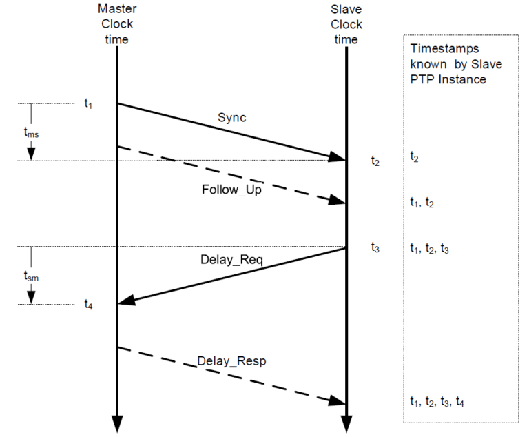
The goal for PTP is to find the offset (difference) between two clocks, called Master Clock and Slave Clock. We use some example numbers to help explain this figure. At a specific moment in time, the Master Clock is December 19 2020 08:05:00.000001000 (8:05 AM and 1000 nanoseconds), and the Slave Clock is December 19 2020 08:05:00.000004000. For simplicity we will use nanoseconds only (1000 ns and 4000 ns). The Master Clock and Slave Clock communicate over a CAT5 copper Ethernet cable. The time for a single bit to propagate over CAT5 is 2 x 10^8 meters/sec. We assume a cable between Master Clock and Slave Clock that is 10 meters in length, thus 50 nanosecond propagation time.
Each time a PTP message is transmitted or received, a timestamp is acquired at a specific point in the message (using the oscillator counter). In the figure, the Master Clock acquires timestamp t1 when a specified bit of the Sync message transmits at the connector. Assume that t1 is 1000 ns. The Slave Clock acquires timestamp t2 when the same bit of the Sync message is received at its connector. Assume that t2 is 4050 ns. The Slave Clock does not know t1 yet, because the Master Clock did not know t1 until after the Sync message transmitted. The Master Clock resolves this by sending t1 in the contents of a Follow_Up message. The dotted line for the Follow_Up message is used to indicate that the message is not timestamped, but is used to transport a timestamp value. At this point the Slave Clock can calculate (t2 – t1), also known as tms. Is the tms value of 3050 sufficient to find the clock offset? No. The tms value is the clock offset (3000 ns) plus the propagation time (50 ns), and the Slave Clock cannot distinguish the two components.
The Delay_Req and Delay_Resp messages are used to find propagation time. The Slave Clock transmits a Delay_Req to the Master Clock, acquiring timestamp t3. Assume that t3 is 305000 ns. The Master Clock acquires timestamp t4 when with Delay_Req is received, and the Master Clock sends t4 back to the Slave Clock in the Delay_Resp message. Assume that t4 is 302050 ns. The Slave Clock can calculate (t4 – t3), also known as tsm, which is -2950 ns for this example. PTP assumes that propagation time is the same in each direction (symmetric). Therefore, the propagation time is calculated as (tms + tsm) / 2, which for this example is (3050 + -2950) / 2 = 50 ns. Now that PTP knows the propagation time, PTP can calculate the clock offset as(tms – ), or 3000 ns. When the Slave Clock subtracts the clock offset from its local time, it is accurately synchronized to the Master Clock time.
The accuracy of the clock synchronization is affected by multiple factors, including a) the accuracy of the timestamping at the correct point in a message, and b) the symmetry of the propagation time. PTP provides a variety of features to customize the implementation of these factors and other aspects. Since different applications (e.g., telecom network, network in a car) have different requirements, PTP specifies the concept of a PTP Profile. The PTP Profile documents the customizations of a specific application, such as requiring some features that are optional in IEEE 1588, and/or prohibiting some features that are not needed. Over the years, this PTP Profile concept is one of the primary reasons for the IEEE 1588 standard’s success, because a wide variety of applications have adapted PTP precisely to their requirements. This has resulted in a large number of PTP Profiles that cover the different applications. One of the aims of IEEE 1588-2019 was to introduce features that align with these PTP Profiles.
The number of new features in IEEE 1588-2019 is too voluminous to describe in this article. The number of PTP Profiles is also too voluminous to describe in this article. Nevertheless, each of the following sections describes an example of a) an application that uses PTP, b) a feature that is needed for that application’s PTP Profile, and c) support for that feature in IEEE 1588-2019.
Advantages and applications
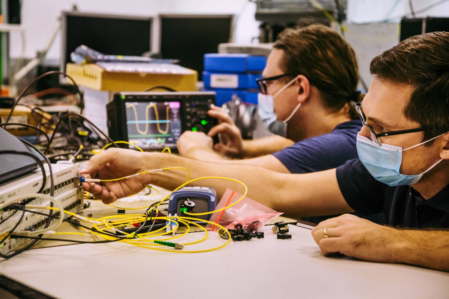
Use case example 1: CERN and White Rabbit
The European Organization for Nuclear Research (CERN) is one of the world’s largest and most respected organizations for scientific research, including well-known particle accelerators such as the Large Hadron Collider (LHC).

As one might expect for an experiment that accelerates particles around a 27-kilometer ring, the LHC uses a large Ethernet network, and the required time synchronization performance is sub-nanosecond. As a result of those requirements, in cooperation with other scientific research organizations, CERN developed a PTP Profile called White Rabbit. White Rabbit specified many innovative techniques, such as enhancements for use of Ethernet hardware clocks, and calibration of asymmetry in fiber optic cabling. The specifications from White Rabbit are incorporated into a new PTP Profile specified in the IEEE 1588-2019 document itself, called the High-Accuracy Delay Request-Response Default PTP Profile. This formalizes White Rabbit as part of the IEEE 1588 standard, which helps to bring best-in-class performance to any application (including non-scientific applications).
Use case example 2: Networks for Internet service (telecom)
Whether at work or at home, many of us understand that we connect our own devices to the Internet using an Ethernet cable (e.g. to a Wi-Fi router). What is sometimes lesser known is that our telecom service provider implements a large network outside of our home/office, and that network is often Ethernet as well. Similar Ethernet networks exist within a 4G/5G base station, to transfer our mobile phone’s data to/from the Internet. These telecom networks require time synchronization, for which they use PTP. The International Telecommunication Union (ITU) is one of the world’s largest standardization organizations for telecom service providers, and its Telecommunication Standardization Sector (ITU-T) specifies multiple PTP Profiles. Past ITU-T standards specified storage of performance statistics in logs, with local measurement in 15-minute and 24-hour periods, accessible at any time by a remote management client. ITU-T’s past logging standards were unrelated to PTP. Nevertheless, during development of IEEE 1588-2019, experts from ITU-T helped to specify this sort of logging for PTP. These specifications meet the needs of ITU-T, but also bring the benefit of ITU-T’s significant field expertise to other applications. This work resulted in the specifications of the Performance Monitoring feature published within IEEE 1588-2019.
Use case example 3: Automotive in-vehicle, and industrial automation +
IEEE 802 is a family of standards for local area networks, such as Ethernet (IEEE 802.3) and Wi-Fi (IEEE 802.11) technologies. As part of that family, the IEEE 802.1 Working Group specifies a PTP Profile within IEEE 802.1AS – Timing and Synchronization for Time-Sensitive Applications. The PTP Profile in IEEE 802.1AS is well known for providing a cost / performance tradeoff that is an excellent fit for time-sensitive applications. What is a time sensitive application? Two examples are the network inside a self-driving car, and the network on a factory’s production floor.
For a self-driving car, devices read input data from the physical world (e.g., radar and cameras to detect objects in front of a car), perform computations on that data, and generate output back to the physical world (e.g., steer the car). These in-vehicle devices communicate over a network, and the devices must be synchronized in time, which is where IEEE 802.1AS comes in. The factory automation example is similar. Robots on the factory floor read input data (e.g. “Is there a bottle in front of me?”), perform computations, and generate output data (e.g., fill the bottle with the factory’s sparkling water). The devices on the factory floor are networked and time synchronized, and IEEE 802.1AS fulfills their requirements.

In both time-sensitive examples above, there is a strong need for IEEE 802.1AS time synchronization to run continuously, even when there is a physical fault like a broken wire. For an industrial factory, lost production time means lost money. For a self-driving car, loss of synchronization can potentially result in safety issues. To meet these reliability requirements, the multiple domain feature has been added to PTP standards. As an example, assume that there are two distinct instances of the PTP protocol (i.e., domains) running in the network. Each domain has a different grandmaster (source of time), and as much as possible, sends time along different paths through the network. Each endpoint (destination of time) uses both domains simultaneously, such that if either domain fails, everything continues to be synchronized. Requirements for multiple domains arose during development of the new revision of the PTP Profile in IEEE 802.1AS-2020. Support for multiple domains required some architectural changes to PTP itself. As a result, both IEEE working groups coordinated closely to add multiple domain support in both IEEE 1588-2019 and IEEE 802.1AS-2020.
Use case example 4: Television broadcast studios
When you watch a live television show such as a news program, you notice many seamless transitions from one scene to another, and the audio is synchronized with the video. Historically, television studios used direct audio/video cabling, but over time many studios have transitioned to use Ethernet networking. In the context of Ethernet, the audio often travels in separate messages than the video. As one would expect, time synchronization is important for these studio networks to precisely control their audio and video. The Society of Motion Picture and Television Engineers (SMPTE) specifies a PTP Profile for this application (ST 2059-2:2015).
Like all Ethernet networks, SMPTE’s network consists of many switches that transfer messages between endpoints (e.g, computers). Each switch supports a variety of protocols, and these protocols need to be configured and updated (typically by IT personnel). Since each switch can potentially come from a different company, ideally the mechanism to configure these switches is a standard (not company-specific). The Internet Engineering Task Force (IETF) provides standards for this purpose, such as SNMP and NETCONF. IEEE 1588-2008 specified a PTP-specific protocol for configuration of PTP in a switch. Although PTP is an important protocol, it is not the only protocol in an Ethernet switch. Organizations like SMPTE need the ability to configure PTP in a switch using protocols like SNMP and NETCONF. As a result, the new revision IEEE 1588-2019 contains architectural changes that significantly clarify and improve the ability to configure PTP using SNMP and/or NETCONF. Using IEEE 1588-2019 as a foundation, work is ongoing in SMPTE and other PTP Profile organizations to establish a clear roadmap for PTP configuration into the future.
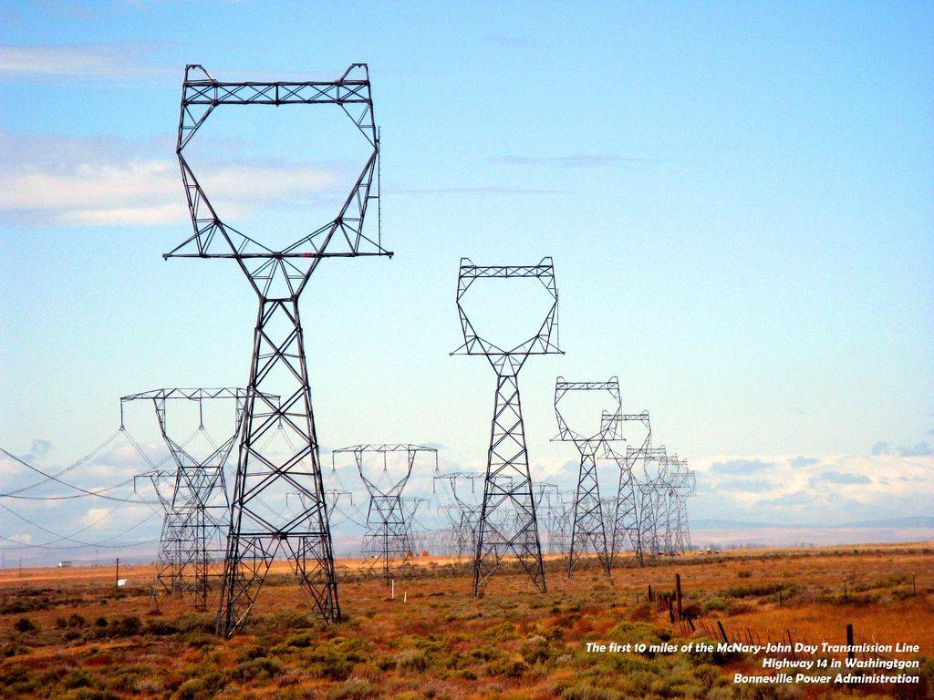
Use case example 5: Electrical distribution
Electricity is often taken for granted in modern society. We need it to be reliable for everything that we do at home or work. The substations, transformers, power lines and other equipment that distribute electricity are more and more complex as technology evolves. As with the applications listed above, power companies often interconnect this electrical equipment using Ethernet networks. To quickly detect and mitigate electrical faults (i.e., keep the lights on), companies use synchrophasor technology to obtain a precise measurement of the magnitude and phase angle of the sine waves found in electricity. It is important to obtain multiple synchrophasor measurements, often thousands of kilometers apart, and those measurements must be accurately synchronized in time. The electrical power industry specifies several PTP Profiles for synchronization, one of which is the IEEE C37.238 standard.
Due to accuracy requirements, IEEE C37.238 specified the addition of Time Inaccuracy information that was not specified in IEEE 1588-2008. As PTP transfers time through the network, each Ethernet switch adds its own inaccuracy to this information. The intent is that every synchrophasor measurement will understand its time synchronization performance. As development proceeded on the new IEEE 1588-2019 revision, other applications saw value in the work done in the electrical industry on Time Inaccuracy. As a result, IEEE 1588-2019 specifies an analogous and slightly enhanced feature, called Enhanced Synchronization Accuracy Metrics. Example: Financial networks In the modern age, financial trading of stocks (and similar assets) are often made by automated systems instead of a human being. Financial trading companies build out large networks that span multiple cities, and due to government regulations and other reasons, the trading actions in each city must be accurately time synchronized. The technologies used in these financial networks are sometimes a mix of local area networking (like IEEE 802.1AS) and telecom networking (like ITU-T). Local area networking often uses multicast communication (one source, many destinations), whereas telecom networking often uses unicast communication (one source to one destination). IEEE 1588-2019 specifies enhancements and clarifications for mixing multicast and unicast communication in a single PTP network. These multicast/unicast clarifications are being used for future development of a PTP Profile for financial