.
Explore the technology specifics:
White Rabbit (WR) is a technology developed at CERN to provide sub-nanosecond accuracy and picoseconds precision of synchronisation for the LHC accelerators chain. It was first used in 2012 and since then has been showcasing its diverse industrial applications outside the field of particle physics. On 16 June, the Institute of Electrical and Electronics Engineers (IEEE) updated the Precision Time Protocol industry-standard (PTP) incorporating the White Rabbit PTP extension and thus maximising its adoption by industry and other partners in their pursuit to build innovative solutions to address world challenges.
CERN developed WR as open-source hardware, with primary adoption by other research infrastructures with similar challenges in highly accurate synchronization of distributed electronic devices. The R&D process and all knowledge gained throughout the development has been made available through CERN's Open Hardware Repository. This gives other organisations and companies the freedom to use and modify existing developments. Through proactive engagement of CERN's Knowledge Transfer group and Beam Controls group, a larger group of companies and organisations connected to the development of hardware, software, and gateware for WR switches and nodes. The WR ecosystem quickly grew to include several organisations, developing open hardware for widespread benefit. This collaborative approach brought improvements to the original concept, allowing CERN to also benefit from the new developments as well.
This new Ethernet-based technology, which ensures sub-nanosecond synchronisation and deterministic data transfer, is now deployed in numerous scientific infrastructures worldwide. It has shown its innovative potential by being commercialised and introduced into different industries, including telecommunications, financial markets, smart grids, space industry and quantum computing.
What is Precision clock synchronisation? +
Source: https://sagroups.ieee.org/1588/news/ieee-1588-2019-evolves-to-better-serve-its-wide-variety-of-applications/
It is the IEEE Standard for a Precision Clock Synchronization Protocol for Networked Measurement and Control Systems, but IEEE 1588 is more commonly known by the protocol that it specifies, the Precision Time Protocol (PTP). The recently published IEEE 1588-2019 is a revision of PTP that was originally published as IEEE 1588-2008. Since 2008, PTP is used in a wide variety of applications around the world, and the 2019 revision evolves PTP to better serve those applications.
The purpose of PTP is to transfer time through a network. A single endpoint in the network acts as the source of time, and PTP transfers that time through various switches/routers to other endpoints. The result is that everything in the network operates with the same time, like multiple human beings each with a synchronized watch. Ethernet is a common network technology for use of PTP, but other networks are applicable such as Wi-Fi and 5G.
Why is a protocol like PTP needed? To help answer that question, let us consider an example implementation of a clock in a device. The device’s clock hardware consists of an oscillator that is specified as 100 million ticks per second (100 MHz). Software in the device reads a counter that tells it how many ticks have occurred since the oscillator was powered on. Without any other information, the software has no idea what time it is, much like a microwave oven that displays “12:00” when powered on. If the device has a network connection, it can receive time from another device over the network. If the devices need to synchronize time accurately, it is not sufficient to use a simple message that contains the current time, because time is changing as the message travels over the network. In addition, oscillators are not perfect, so in reality one device’s 100 MHz oscillator can run at 99.990 MHz, and another device’s oscillator can run at 100.010 MHz. This can cause times to eventually drift apart, and that drift is affected by environmental factors like temperature. The PTP protocol operates continuously to resolve these challenges.
There are many details in the PTP specifications, but the following figure helps to demonstrate the fundamentals.
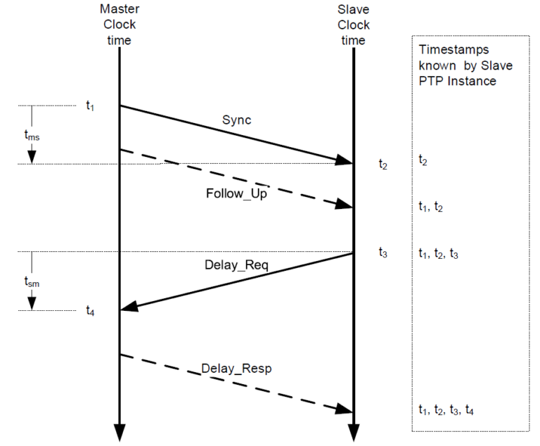
The goal for PTP is to find the offset (difference) between two clocks, called Master Clock and Slave Clock. We use some example numbers to help explain this figure. At a specific moment in time, the Master Clock is December 19 2020 08:05:00.000001000 (8:05 AM and 1000 nanoseconds), and the Slave Clock is December 19 2020 08:05:00.000004000. For simplicity we will use nanoseconds only (1000 ns and 4000 ns). The Master Clock and Slave Clock communicate over a CAT5 copper Ethernet cable. The time for a single bit to propagate over CAT5 is 2 x 10^8 meters/sec. We assume a cable between Master Clock and Slave Clock that is 10 meters in length, thus 50 nanosecond propagation time.
Each time a PTP message is transmitted or received, a timestamp is acquired at a specific point in the message (using the oscillator counter). In the figure, the Master Clock acquires timestamp t1 when a specified bit of the Sync message transmits at the connector. Assume that t1 is 1000 ns. The Slave Clock acquires timestamp t2 when the same bit of the Sync message is received at its connector. Assume that t2 is 4050 ns. The Slave Clock does not know t1 yet, because the Master Clock did not know t1 until after the Sync message transmitted. The Master Clock resolves this by sending t1 in the contents of a Follow_Up message. The dotted line for the Follow_Up message is used to indicate that the message is not timestamped, but is used to transport a timestamp value. At this point the Slave Clock can calculate (t2 – t1), also known as tms. Is the tms value of 3050 sufficient to find the clock offset? No. The tms value is the clock offset (3000 ns) plus the propagation time (50 ns), and the Slave Clock cannot distinguish the two components.
The Delay_Req and Delay_Resp messages are used to find propagation time. The Slave Clock transmits a Delay_Req to the Master Clock, acquiring timestamp t3. Assume that t3 is 305000 ns. The Master Clock acquires timestamp t4 when with Delay_Req is received, and the Master Clock sends t4 back to the Slave Clock in the Delay_Resp message. Assume that t4 is 302050 ns. The Slave Clock can calculate (t4 – t3), also known as tsm, which is -2950 ns for this example. PTP assumes that propagation time is the same in each direction (symmetric). Therefore, the propagation time is calculated as (tms + tsm) / 2, which for this example is (3050 + -2950) / 2 = 50 ns. Now that PTP knows the propagation time, PTP can calculate the clock offset as(tms –
The European Organization for Nuclear Research (CERN) is one of the world’s largest and most respected organizations for scientific research, including well-known particle accelerators such as the Large Hadron Collider (LHC).

As one might expect for an experiment that accelerates particles around a 27-kilometer ring, the LHC uses a large Ethernet network, and the required time synchronization performance is sub-nanosecond. As a result of those requirements, in cooperation with other scientific research organizations, CERN developed a PTP Profile called White Rabbit. White Rabbit specified many innovative techniques, such as enhancements for use of Ethernet hardware clocks, and calibration of asymmetry in fiber optic cabling. The specifications from White Rabbit are incorporated into a new PTP Profile specified in the IEEE 1588-2019 document itself, called the High-Accuracy Delay Request-Response Default PTP Profile. This formalizes White Rabbit as part of the IEEE 1588 standard, which helps to bring best-in-class performance to any application (including non-scientific applications).
Whether at work or at home, many of us understand that we connect our own devices to the Internet using an Ethernet cable (e.g. to a Wi-Fi router). What is sometimes lesser known is that our telecom service provider implements a large network outside of our home/office, and that network is often Ethernet as well. Similar Ethernet networks exist within a 4G/5G base station, to transfer our mobile phone’s data to/from the Internet. These telecom networks require time synchronization, for which they use PTP. The International Telecommunication Union (ITU) is one of the world’s largest standardization organizations for telecom service providers, and its Telecommunication Standardization Sector (ITU-T) specifies multiple PTP Profiles. Past ITU-T standards specified storage of performance statistics in logs, with local measurement in 15-minute and 24-hour periods, accessible at any time by a remote management client. ITU-T’s past logging standards were unrelated to PTP. Nevertheless, during development of IEEE 1588-2019, experts from ITU-T helped to specify this sort of logging for PTP. These specifications meet the needs of ITU-T, but also bring the benefit of ITU-T’s significant field expertise to other applications. This work resulted in the specifications of the Performance Monitoring feature published within IEEE 1588-2019.
IEEE 802 is a family of standards for local area networks, such as Ethernet (IEEE 802.3) and Wi-Fi (IEEE 802.11) technologies. As part of that family, the IEEE 802.1 Working Group specifies a PTP Profile within IEEE 802.1AS – Timing and Synchronization for Time-Sensitive Applications. The PTP Profile in IEEE 802.1AS is well known for providing a cost / performance tradeoff that is an excellent fit for time-sensitive applications. What is a time sensitive application? Two examples are the network inside a self-driving car, and the network on a factory’s production floor.
For a self-driving car, devices read input data from the physical world (e.g., radar and cameras to detect objects in front of a car), perform computations on that data, and generate output back to the physical world (e.g., steer the car). These in-vehicle devices communicate over a network, and the devices must be synchronized in time, which is where IEEE 802.1AS comes in. The factory automation example is similar. Robots on the factory floor read input data (e.g. “Is there a bottle in front of me?”), perform computations, and generate output data (e.g., fill the bottle with the factory’s sparkling water). The devices on the factory floor are networked and time synchronized, and IEEE 802.1AS fulfills their requirements.

In both time-sensitive examples above, there is a strong need for IEEE 802.1AS time synchronization to run continuously, even when there is a physical fault like a broken wire. For an industrial factory, lost production time means lost money. For a self-driving car, loss of synchronization can potentially result in safety issues. To meet these reliability requirements, the multiple domain feature has been added to PTP standards. As an example, assume that there are two distinct instances of the PTP protocol (i.e., domains) running in the network. Each domain has a different grandmaster (source of time), and as much as possible, sends time along different paths through the network. Each endpoint (destination of time) uses both domains simultaneously, such that if either domain fails, everything continues to be synchronized. Requirements for multiple domains arose during development of the new revision of the PTP Profile in IEEE 802.1AS-2020. Support for multiple domains required some architectural changes to PTP itself. As a result, both IEEE working groups coordinated closely to add multiple domain support in both IEEE 1588-2019 and IEEE 802.1AS-2020.
When you watch a live television show such as a news program, you notice many seamless transitions from one scene to another, and the audio is synchronized with the video. Historically, television studios used direct audio/video cabling, but over time many studios have transitioned to use Ethernet networking. In the context of Ethernet, the audio often travels in separate messages than the video. As one would expect, time synchronization is important for these studio networks to precisely control their audio and video. The Society of Motion Picture and Television Engineers (SMPTE) specifies a PTP Profile for this application (ST 2059-2:2015).
Like all Ethernet networks, SMPTE’s network consists of many switches that transfer messages between endpoints (e.g, computers). Each switch supports a variety of protocols, and these protocols need to be configured and updated (typically by IT personnel). Since each switch can potentially come from a different company, ideally the mechanism to configure these switches is a standard (not company-specific). The Internet Engineering Task Force (IETF) provides standards for this purpose, such as SNMP and NETCONF. IEEE 1588-2008 specified a PTP-specific protocol for configuration of PTP in a switch. Although PTP is an important protocol, it is not the only protocol in an Ethernet switch. Organizations like SMPTE need the ability to configure PTP in a switch using protocols like SNMP and NETCONF. As a result, the new revision IEEE 1588-2019 contains architectural changes that significantly clarify and improve the ability to configure PTP using SNMP and/or NETCONF. Using IEEE 1588-2019 as a foundation, work is ongoing in SMPTE and other PTP Profile organizations to establish a clear roadmap for PTP configuration into the future.
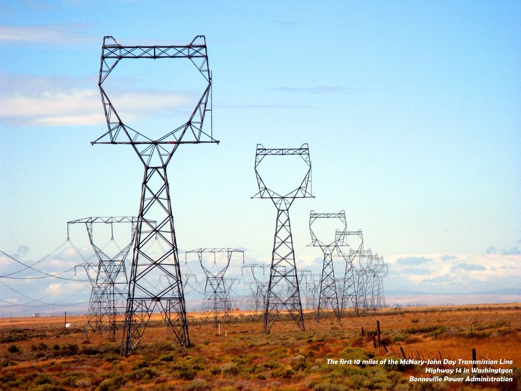
Electricity is often taken for granted in modern society. We need it to be reliable for everything that we do at home or work. The substations, transformers, power lines and other equipment that distribute electricity are more and more complex as technology evolves. As with the applications listed above, power companies often interconnect this electrical equipment using Ethernet networks. To quickly detect and mitigate electrical faults (i.e., keep the lights on), companies use synchrophasor technology to obtain a precise measurement of the magnitude and phase angle of the sine waves found in electricity. It is important to obtain multiple synchrophasor measurements, often thousands of kilometers apart, and those measurements must be accurately synchronized in time. The electrical power industry specifies several PTP Profiles for synchronization, one of which is the IEEE C37.238 standard.
Due to accuracy requirements, IEEE C37.238 specified the addition of Time Inaccuracy information that was not specified in IEEE 1588-2008. As PTP transfers time through the network, each Ethernet switch adds its own inaccuracy to this information. The intent is that every synchrophasor measurement will understand its time synchronization performance. As development proceeded on the new IEEE 1588-2019 revision, other applications saw value in the work done in the electrical industry on Time Inaccuracy. As a result, IEEE 1588-2019 specifies an analogous and slightly enhanced feature, called Enhanced Synchronization Accuracy Metrics. Example: Financial networks In the modern age, financial trading of stocks (and similar assets) are often made by automated systems instead of a human being. Financial trading companies build out large networks that span multiple cities, and due to government regulations and other reasons, the trading actions in each city must be accurately time synchronized. The technologies used in these financial networks are sometimes a mix of local area networking (like IEEE 802.1AS) and telecom networking (like ITU-T). Local area networking often uses multicast communication (one source, many destinations), whereas telecom networking often uses unicast communication (one source to one destination). IEEE 1588-2019 specifies enhancements and clarifications for mixing multicast and unicast communication in a single PTP network. These multicast/unicast clarifications are being used for future development of a PTP Profile for financial
Explore the technology specifics:
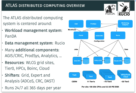
Rucio is a project that provides services and associated libraries for allowing scientific collaborations to manage large volumes of data spread across facilities at multiple institutions and organisations. Rucio was originally developed to meet the requirements of the high-energy physics experiment ATLAS, and now is continuously extended to support the LHC experiments and other diverse scientific communities.
Rucio offers advanced features, is highly scalable, and modular. It is a data management solution that covers the needs of different communities in the scientific domain (e.g., HEP, astronomy, biology).
Having demonstrated very large scale data management capabilities, Don Quijote (DQ2), the ATLAS Distributed Data Management System used for HEP experiments at CERN had reached its limits in terms of scalability. The primary concerns were the requirement of a large number of support staff to operate. difficulty in interfacing with new technologies To address these very scaling requirements for HEP experiments, Rucio as a Distributed Data Management System, was developed. Drawing benefits from advances in Cloud & Big Data computations, it relies on a conceptual data model to ensure system stability. Dataflow autonomy and automation are the key design principles guiding the development of Rucio. To reduce the operational overheads of the support staff, it employs an automation framework and also accounts for newer use cases & user requirements of the LHC Run2 experiments.
What can Rucio do? + Standing on the shoulders of its predecessor, ATLAS, the capabilities of Rucio are currently leveraged for:
- Storage of detector data, simulator data, and user data
- Unified interfacing of heterogenous network & storage infrastructure
- Support for newer protocols in Storage & Network using plugins
- Data Recovery
- Adaptive Replication
Rucio is based on a distributed system architecture & can be sectioned into four major layers:
Clients
The clients layer consists of components such as the command line clients (CLI), Python clients, and the Javascript-based web user interface and configuration.
Server
The server layer serves the purpose of authentication & provides a common API for interaction with clients & other external application, as also the Web UI.
Core
This layer consists of all the Rucio-level abstractions that are explained at length in the Concepts section.
Daemons
The daemons layer takes care of all the asynchronous & continuous workflows in the background.
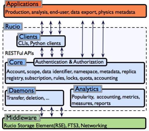
In addition to the four main layers, we have the storage resources & transfer tools, as well as the underlying persistent layers. These are represented in the architecture diagram by the different queuing systems, transactional relational databases, & analytics storage on non-relational databases.
Storage & Transfer Tools layer
The Storage layer is responsible for the various interactions with different grid middleware tools & storage systems. The transfer tool interface is a feature of Rucio that enables the daemons to submit, query, and cancel transfers generically & independently from the actual transfer service being used. This layer is not a software that resides in a datacenter but is more representative of the various abstractions in a storage system. It can be configured dynamically & centrally to suite requirements.
Persistence Layer
This is the layer responsible for keeping all the data & application states for all daemons. Also known as the catalog, it requires a transactional database. The persistence layer supports many different types of transactions relational database management systems such as SQLite, MySQL, PostgreSQL, or Oracle
What can Rucio do? Standing on the shoulders of its predecessor, ATLAS, the capabilities of Rucio are currently leveraged for:
- Storage of detector data, simulator data, and user data
- Unified interfacing of heterogenous network & storage infrastructure
- Support for newer protocols in Storage & Network using plugins
- Data Recovery
- Adaptive Replication
The technology can have many applications in:
- Large data storage, discovery - any data federation
- Moving data from public clouds to private clouds with a single API
Ultra-compact laser system designed for high-power output with spectral purity, capable of operating at virtually any wavelength.
The low-cost single frequency Brillouin/Raman laser technology exploits the Brillouin scattering effect to refine continuous wave integrated laser sources to their Fourier limit, producing ultra-narrow linewidths with remarkable stability. Unlike traditional single-frequency lasers, which require intricate optical arrangements and feedback control systems, the technology offers a streamlined, automated solution that simplifies the conversion of multi-mode lasers into single-frequency outputs.
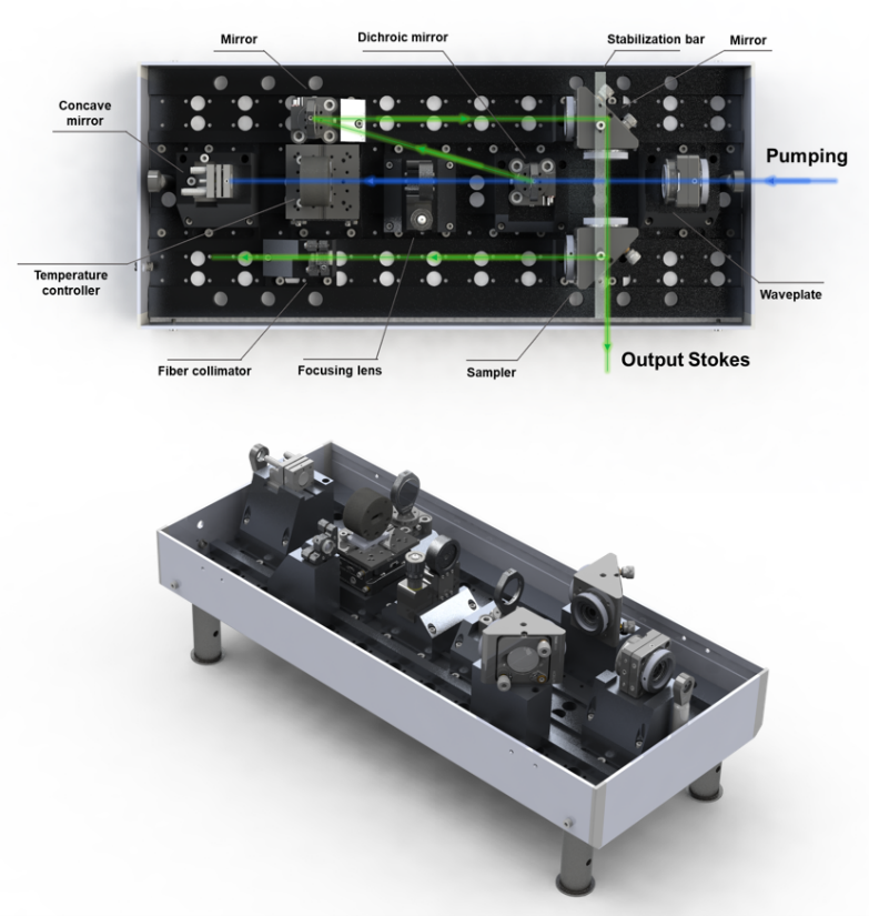
The core innovation lies in the utilization of a Brillouin process within solid-state media such as Raman crystals, achieving single-mode operation without the need for additional optics or electro-mechanical controls. The laser operates within a Fabry-Pérot resonator setup, meticulously constructed to ensure intrinsic stability. This design enables the device to maintain a stable single-frequency output by carefully managing the pump laser focusing and selecting Raman media with optimal characteristics. The system achieves a high Raman gain in a single pass, essential for efficient single-frequency lasing. The choice of Raman crystals such as synthetic diamond or Ba(NO₃)₂ provides an exceptionally narrow linewidth, significantly enhancing spectral purity.
Advantages
Precision and Stability
Achieves high precision and stability without the need for complex stabilization techniques, ideal for applications requiring long coherence lengths.
Cost Effectiveness
Reduces the cost per unit significantly by leveraging existing laser sources and simplifying the conversion process.
Versatility
Offers multiple single-frequency outputs at various wavelengths simultaneously, enhancing its applicability across different fields.
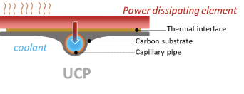
Ultralight Cold Plate (UCP) can be used for the cooling of power dissipating elements, based on micro-macro vascular pipes embedded in high thermal conductive carbon substrate.
The UCP was developed for sensors/chips thermal management of the new Inner Tracking System (ITS) that has been installed in the ALICE experiment at CERN in 2022.
UCP can have applications in drug production and other areas with need for cryogenics expertise.
Explore the technology specifics:
The CERN technology consists in an Ultralight Cold Plate (UCP) for the cooling of power dissipating elements, based on micro-macro vascular pipes embedded in high thermal conductive carbon substrate.
The UCP is made of a high thermal conductivity carbon plate, embedding ultralight polyimide cooling pipes. Different carbon materials are laid-up in the plate thickness to enhance thermal performance and guarantee structure integrity. The dissipating elements that need to be cooled down are in thermal contact with the UCP through glue or thermal interface materials. The heat is transferred from the dissipating elements into the cooling pipes by the carbon substrate and is removed by the coolant flowing in the pipes. Several coolants have been used, from single phase liquid (water) to two-phase evaporative (C4F10), and different ones are being tested (CO2).
- The technology has been fully developed at CERN, within the ALICE collaboration. UCP serial production (>300 units) was based at CERN in the ALICE Composite laboratory.
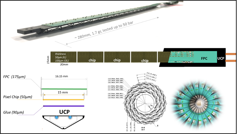
- The UCP was developed for sensors/chips thermal management of the new ALICE Inner Tracking System (ITS) that has been installed in ALICE in 2022. The ALICE ITS is a 12.5 Giga-Pixel camera consisting of seven cylindrical detection layers equipped with monolithic pixel sensors that covers a ~10m2 surface and dissipate about 400W/m2. The UCP for the ITS covers a length of 28cm for the three innermost vertex layers and up to 1.5 meter for the 4 outermost tracker layers. The UCP design had to comply not only with large heat removal capacity but also with the ALICE ITS tight requirements in term of extremely low material budget and radiation hardness. The UCP design has been adopted in another detector in ALICE, the Muon Forward Tracker. In addition, three other HEP Experiments have used the same UCP: NA61, MDP NICA and SPhenix.
The technology is unique because of its ofering.
- No similar technologies are present in the market.
- The UCP offers unique cooling performance and minimum material thickness and weight. The use of an optimised carbon plies lay-up combined with non-metallic tubes running in between the plies is a completely novel feature. The UCP are produced using a non-conventional manufacturing process for composite material tailored to this specific application. Several tests have been performed to optimise the lay-up of the different carbon plies and the embedding of the polyimide pipes, for the construction of the Cold Plate. Unidirectional High Thermal Conductive (HTC) carbon prepreg (pre-polymerised), pyrolytic graphite foil (PGF) and quasi-isotropic structural carbon lamina (Carbon fleece) are laid up in a double mould that allows at the same time the embedding of the polyimide pipes. After the manual lay-up of the different components, the UCP undergoes a curing process, based on heating and pressure cycles, required for the resin polymerisation and consolidation. Co-curing of carbon laminates and embedded pipes permits to optimise their thermal interfaces by minimising the amount of glue.
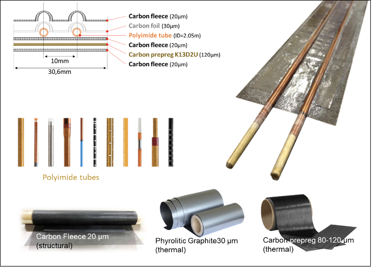
- The resin system for the CFRP is cyanate ester resin, which is preferable to epoxy resin for its low humidity absorption and better dimensional stability in time. The choice of the material for the cooling pipes embedded in the structure is driven by the requirement of low material budget, high thermal conductivity, and radiation hardness. A suitable compromise among these requirements is the use of a plastic tube with a very thin wall. Polyimide shows high radiation hardness up to at least 107 Gy and high radiation length, X0 ≈ 28cm. Small diameter pipes with 1.024mm (2.67mm) inner diameter and 25µm (64µm) thin walls have been used in two of the present applications in HEP detectors. A record ultralight cold plate weighing only 1.7 gram to cover a surface of ~280mmx15mm has been achieved including polyimide pipes of 1mm diameter and a structural stiffener also in carbon fibre for mechanical support.
- In the UCP the pipes are always embedded in the carbon structure and never directly exposed. In this way their intrinsic fragility and tendency to pinch and buckle under localised load does not affect their use. The connection to feeding lines is through a glued joint between polyimide pipes and fittings. The behaviour of the pipes and fittings was qualified under high pressure loads and polyimide erosion due to coolant (water) flow in radiation environment has been assessed. The polyimide pipes are commercially available on the market with a large variety of features and with an extremely tight quality control, being these pipes used in the medical field for vascular catheters. Different pipe sizes down to 50 micron in diameter and 6 micron wall are available on the shelf, as well local braided and coiled reinforcement for bending torsion and pressure increased performances; or specific laser machined features for OD reduction and connectivity. This large range of pipe properties open the possibility of further developments of the UCP technology, towards micro pipes (ID < 1mm) from one side and large surface coverage ( > 1.5m) on the other side, while both these R&D lines are being pursued at CERN.
The technology can have many applications in:
- High-energy physics
- Cryogenics
- Drug production
Reading material and records:
- Technical paper_CGargiulo and Bell_ https://indico.cern.ch/event/810687/contributions/3452034/attachments/1877493/3092189/20190710_CGargiulo_Bell.pdf
- Technical upgrade re CLIC– ALICE_ITS_Upgrade_CGARGIULO- (Relevant info slide 4 onwards)_ https://indico.cern.ch/event/388177/contributions/1820532/attachments/775930/1064037/20150528_CLIC-ALICE_ITS_Upgrade_CGARGIULO.pdf
- https://iopscience.iop.org/article/10.1088/1748-0221/13/08/T08003
- https://cds.cern.ch/record/1625842/files/0954-3899_41_8_087002.pdf
CERN technologies for you
|
In running the world's largest particle physics experiments and operating in unparalleled extreme conditions, CERN has developed unique expertise in multiple areas ranging from superconductivity, microelectronics, cryogenics, vacuum, data monitoring and management tools and much more. Learn more about the CERN technologies available under this programme, and how it could benefit your company. |
 |
Explore the technology specifics:
SLB is a low-cost laser that produces a non-diffractive beam (NDB) that has very low diverge and can maintain the Bessel-like beam and spot sizes for long distances.
What is non diffractive beam?
A non-diffractive beam was first proposed by Durnin et al. in 1978 as a light beam having a transverse intensity distribution that can be modeled using a Bessel function. The beam profile remains unchanged even if it propagates over a long distance.
Current methods of generating Bessel beams are using Axicons, annulus holes, holography methods and using fibres. However, the major shortfall of these current state of art methods are that they are limited to very short distances.

What is a bessel beam? A Bessel beam is a focus high intensity beam a at the centre. There is central spot where all the energy is concentrated. The intensity distribution is not uniform or controllable.


Where as the Gaussian beam profile looks like →


So, why is this called the Structured Laser Beam? The characters of the CERN technology is very similar to the Bessel Beam. However, the uniqueness is that the rings around the central spot can be controlled and tuned. The size of the central beam, the divergence of the full beam and the distribution of the rings - all of them adjustable based on applications.


SLB Principle of operations A special wavefront shape is created by using different optical paths by using very high index optical elements.

The beam profile generated after the generator is a continuous line

The SLB self reconstructs when the path is an obstacle. This has many applications where the laser has to travel where there are either known obstacles or unknown ones. For example, in medical applications (where there might be a known obstacle) or in telecommunications – free space optics where there might be unknown obstacles.

The benfit of using the technology is:
- Low-cost
- Extremely compact spot size and very low divergence
- Non-diffractive over long distances
- Self-constructive after obstacles
- Robust to jitter, vibrations, and variations on the angle of the input beam
The technology can have many applications in:
- Alignment - Original use case at CERN for ultra precision alignment
- Metrology
- Expected cost
- Interferometry
- Communication
- Optical tweezers
- Marking of packaging
A startup from Netherlands is using SLB for engraving/marking applications. They have a working. Prototype and customers who are trialing their product for marking boxes.

Connecting Startups with Cutting-Edge Technology and Investment


Why Join the CVC Programme?


Explore CERN Technologies
 Discover the vast array of CERN technologies available to help accelerate your venture. Explore how our cutting-edge solutions can be applied to your specific industry and drive your startup’s success.
They can have applications in varying fields – optical communications, metrology, cryogenics, aerospace, drug-production, quantum computing, data storage and more.
